Engineering
3D inspection application
Characteristics
- Providing basic comparison functions at a reasonable price
- Inspection result data can be output in csv and IGES
Related functions
- Property (The following features related to the shape of the mesh are displayed.)
- Surface area, Volume
- Center of gravity
- Size(Length of the range where the mesh exists in each coordinate axis direction.)
- Number of shells
- Number of shell boundaries
- Average / Maximum / Minimum edge length
- Distance (Measure the distance between two vertices.)
- Coordinates (Display coordinate values.)
- Circle Radius (Measure the diameter.)
- Distance Contour (Color map display of distance distribution.)
- Thickness Inspection (Color map display of mesh thickness.)
- Display Section Lines
- Find Path (Display the shortest edge ??string that connects two vertices by following an edge.)
- Crease Detection
Case study
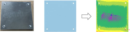
An example of displaying a color map of the difference between a mesh created from measured data of a metal plate and a flat surface
Data correction application
Characteristics
- Powerful polygon editing function available
- Automatic mesh shaping function: With one click, the mesh derived from the measurement is automatically cleaned and shaped into a smooth mesh. No operation know-how or complicated operation is required.
Related functions
- Cleaning (Inspect and repair incorrect parts of the mesh.)
- Defeature (Remove through holes, blind holes, dents, protrusions, self-intersections, etc.)
- Smoothing (Make smooth by removing fine irregularities on the surface of the mesh.)
- Simplify (Reduce the number of faces in the mesh.)
- Subdivision (The bulge of a face is estimated from the bending of the surrounding faces, and the face is divided so that it rides on the bulge.)
- Remesh (Reconstruct the mesh so that the faces are close to equilateral triangles.)
- Cut (Cut the mesh with a plane. You can remove one side of the cut or leave both sides.)
- Boolean Operation
- Flip Shells (Turn over the front and back sides of the specified shell.)
- Delete Shells
- Scaling
- Arrange Shells (Arrange shells according to various conditions.)
- Fill Caves (Detect through holes and blind holes of a mesh and fill them.)
- Reshape Hole (Compensate for the irregularities in the round hole to round.)
- Make Flat / Cylindrical (The specified area is reshaped into a flat or cylindrical surface.)
- Remove Protrusion
- Projection Solid (Sweep the open shell to a plane to create a solid shell.)
- Difference Solid (The difference between the mesh and the external file’s mesh is created as solid shells.)
- Transplant (Embed another shell in the hole.)
- Loop Cut (Cut the mesh with the closed polyline drawn on the mesh.)
- Reshape CT mesh (reshape the mesh derived from CT measurement.)
- Reshape Optical mesh (reshape the mesh derived from Optical measurement.)
- Delete Faces
- Delete Boundary Faces (Delete faces near the shell boundary.)
- Fill Holes (Fill the holes on the mesh surface.)
- Extension (Extend the mesh smoothly at the shell boundary.)
- Flip Edge (Replace the edge using the quadrilateral diagonal formed by two triangles on either side of the edge.)
- Merge Vertices (Move a vertex to its adjacent vertex, and combine the two vertices into one vertex.)
- Remove Acute Triangles (Detects acute triangles and removes them.)
- Divide Faces (Divide the face by the drawn line.)
- Segmentation (Divide the mesh into multiple color-coded areas based on shape feature.)
- Edit Segment Boundary (Merge segments, or smooth a segment boundary.)
- Wrapping (Create a new mesh using only the outside of the mesh.)
- Thicken (Add thickness to the shell.)
- Offset (Create a mesh that is a fixed distance away from the original mesh.)
- Fill Region (Estimate the surface that passes through the shape around the hole, and use that surface to fill the hole.)
- Advanced Self-intersection Removal (Fix complex self-intersections.)
- Sharpen (Makes a rounded ridge area into a sharp edge)
- Trim (Trim the mesh with the drawn lines.)
Case study
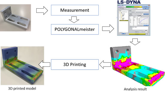
[ Edit mesh for analysis ]
Clean, simplify, and remesh the mesh so that it can be imported into the analysis system. By supplying an appropriate polygon model, the man-hours for creating a finite element creation are reduced and the analysis calculation time is shortened.
Example 1: Analysis of measured machine parts
From “Automatic correction and reshaping function for measured polygon data” published in the July 2020 issue of “Die and Mold Technology"
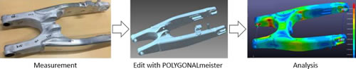
| Edit polygon model using POLYGONALmeister to create analysis model | Convert a CAD surface model using a commercially available SW, and then create an analysis model | |
|---|---|---|
| Accuracy (difference from the original shape) |
About 0.1mm | About 0.5mm |
| Operation time | About half a day (1 hour:Reshape CT mesh + 1.5 hour: other editting operation) |
About 1 week (Estimated time by experienced people ) |
| Price | 0.8 million yen | About 2.5 million yen |
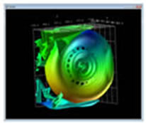
Example 2: Analysis of measured bottle
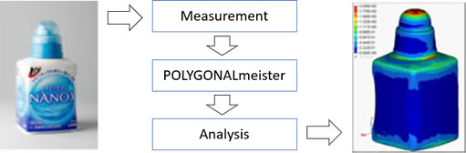
Data provided by: Lion Corporation
Example 3: Colored 3D printing of analysis results
<
Data provided by: JSOL Corporation
[ 3D Print ]
For the purpose of education, presentation, evaluation of analysis results, etc., the mesh of analysis results created with AVS / Express was formed with a 3D printer.
Data provided by: Cybernet Systems Co., Ltd.
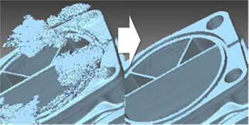
[ Edit mesh derived from industrial CT ]
- Mesh with more than 100 million polygons can be handled
- Data size (number of faces) reduction
- Correction of artifact part
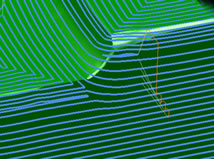
[ Editing for CAM with mesh as input ]
When calculating tool paths with CAM from measurement-derived polygon meshes, the following problems may occur.
- It takes a lot of time to calculate the tool path.
- Triangles stand out on the surface of the cut mold.
Good quality processing results can be obtained by processing the polygon mesh after smoothing or subdividing it.
In addition, the simplification shortens the tool path calculation time.
Example: Example of shortening tool path calculation time by simplification
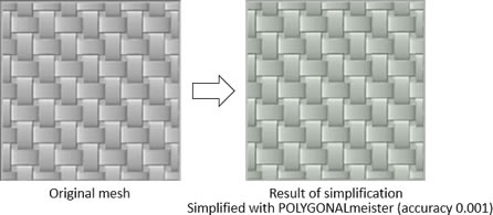
Simplified with POLYGONALmeister (accuracy 0.001)
Comparison of tool path calculation time before and after simplification
| Original mesh | Result of simplification | |
|---|---|---|
| Number of faces | 4,650,000 | 280,000 |
| Calculation time | 18min.30sec. | 3min.15sec. |
Profile processing. Ball end tool with a diameter of 1. XY pitch 0.05.
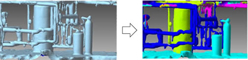
[ Scan data in a factory ]
By using the segmentation function of POLYGONALmeister, it is possible to efficiently divide the complicated data in the factory into parts.