Function(CAM)
![]()
![]()
![]()
![]()
![]()
![]()
![]()
![]()
Function(CAM)
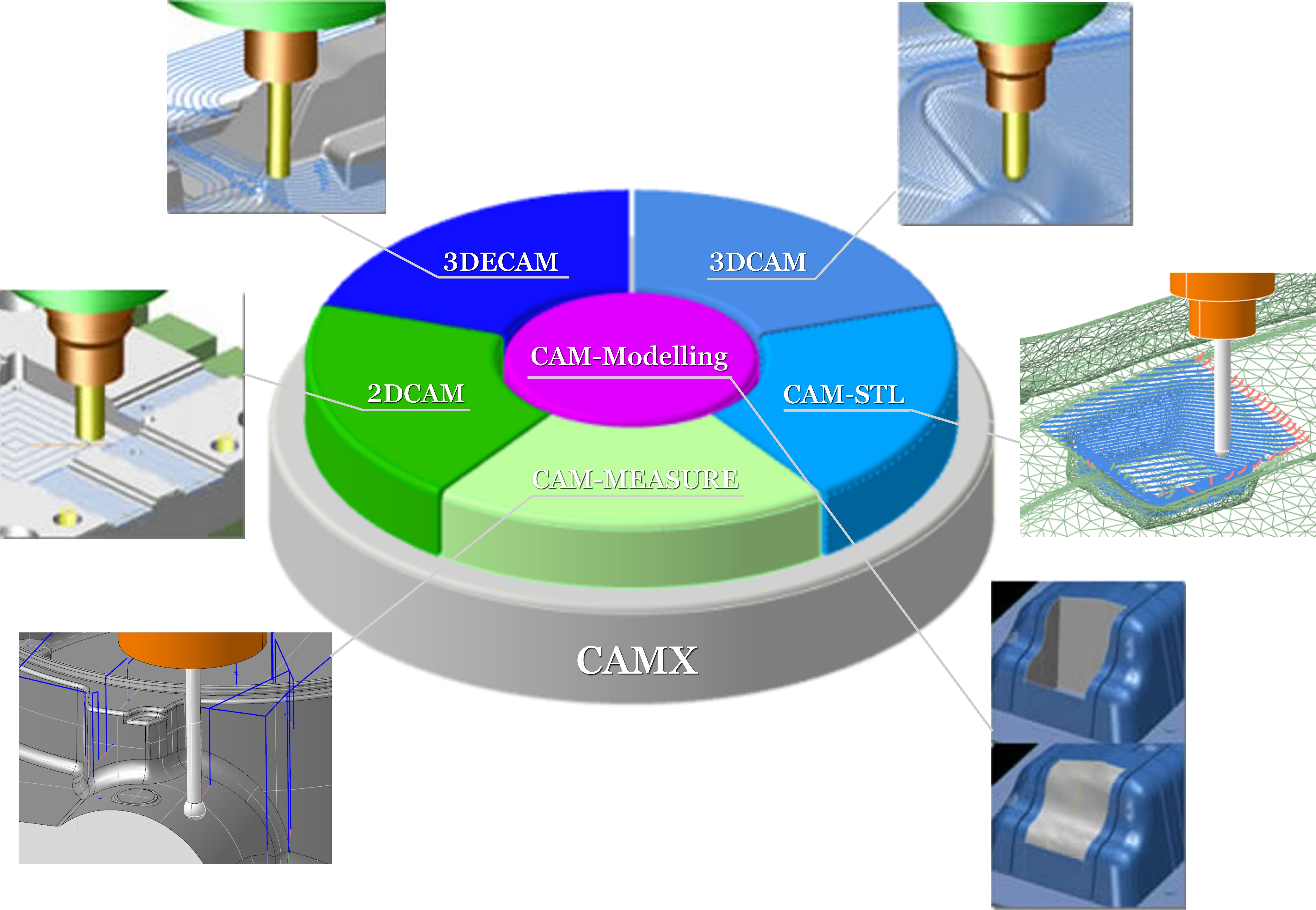
CAMX is a CAD/CAM system that consists of a CAM engine based on CADmeister/CAM. The CAM engine has been manufactured by C&G SYSTEMS INC. a recognized company for machining resin molds. CADmeister/CAM is a proven system for press die machining. Thus, CAMX is added of high-speed, high-grade, and highly-efficient machining methods and optimization pass to conventional proven methods. It can respond to a wide variety of users' needs.
CAMX supports a variety of machining modes: 2DCAM (hybrid 2D CAM), 3DCAM (hybrid 3DCAM), 3DECAM (GP-CAM), and CAM-STL (CAM supporting STL Models). Furthermor, CAMX is equipped with CAM-MEASURE (on-machine measurement). Thus, it can create paths that fit various types of machining such as holing in an assimilated environment of 2D and 3D machining. Furthermore, the modelling capability of streamlining CAM operations as well as the capabilities of editing and analyzing surfaces improve the machining efficiency and the quality of paths.
3DECAM enables high-speed, high-grade, and highly-efficient machining due to CAM-TOOL engine (GP-CAM) supported by C&G SYSTEMS INC. (which has an alliance with UEL Corporation.)
 The "Contour_Rough" command
 The "Contour_Rough_Primary Machining" command
 The "Contour_Finish" command
 The "Concave_Uncut Portion_Contour" command
 The "Concave_Uncut Portion" command
Highly Efficient Rough Machining Enabled by a High-Feed Cutter
The “HighlyEfficientRoughMachining” command enables smooth machining free from bends and thus improves machining efficiency.
The “HighlyEfficientRoughMachining” command can specify an amount of allowance to keep a cutting tool ona cut-subject area without coming off from the area. Thus, it can reduce oscillations caused by the cutting tool.
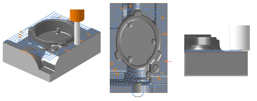
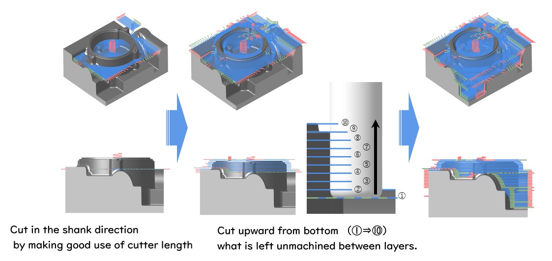
Z-level High Efficiency Rough Cutting (Climb-up Roughing)
The Z-levelHighEfficiencyRoughCutting ” command enables a highly efficient machining that makes good use of an external peripheral edge of cutting tool in order to increase cut quantity into the direction of shank and cut upward from what is left unmachined between layers.
The Z-levelHighEfficiencyRoughCutting ” command enables the System to adjust automatically a cutting pitch of cutting tool in the direction of diameter on the basis of considerations of loads upon a cutting tool due to cutting along a path upward from bottom.
The Z-levelHighEfficiencyRoughCutting ” command enables the System operators to stabilize an amount of cutting in the direction of diameter in order to create a cutting path where loads upon a cutting tool are reduced, and thus the command stabilizes machining.
Create Paths by Using Cast Metal (Stock Model)
The “ContourRoughMachining” command enables the System operators to locate machining areas in a cast metal (referred to as "Stock Model") through computation, and thus create wasteless paths for rough machining.
The System operators can define cutting paths and cutting conditions that match a cutter size by executing the “ContoursRoughMachining” command in coordination with the “ToolingInterferenceAvoidance” command in order to perform efficient machining.
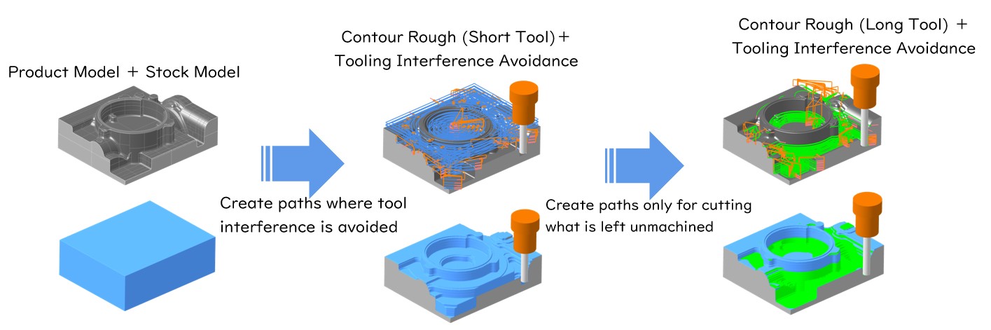
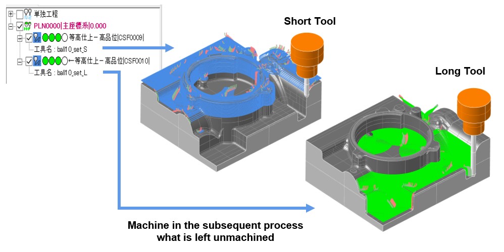
Tool Interference Avoidance
The "FinishMaching" command creates optimum machining paths that do not cause tool interference.
There are parts left unmachined in order to keep cutting tools from causing interference. The residues are machined in the subsequent cutting phase where cutting tools with a long edge are used. The “FinishMachining” command enables the System operators to create cutting paths that meet a cutting pitch and other cutting conditions of the subsequent phase.
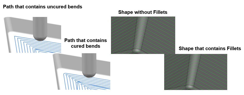
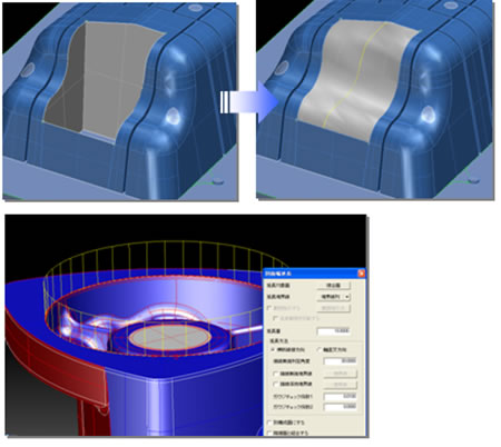
Cure Path Bends and Corners
The “CurePathBendsandCorners” command creates bending paths that decelerate feed rates around arcs. The command thus machines without intervals between pitches left unmachined.
The “CurePathBendsandCorners” command creates a Fillet of specified R at concave portions that enables a path to prevent a cutting tool from causing a Two-Point contact.
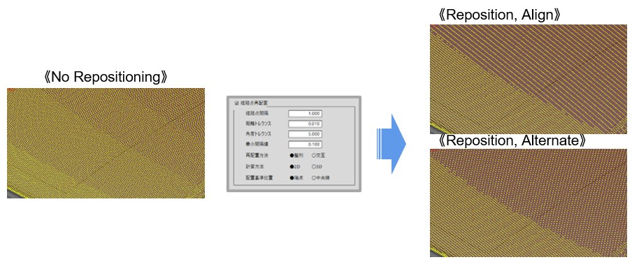
Path Points Reposition
The “PathPointsReposition” command creates machining data that contains Path Points evenly positioned along a path in accordance with the curvature of product shape.
The “PathPointsReposition” command reduces a gap of machining speed among neighboring paths by adjusting Path Points positions based upon considerations of the characteristics of machine tool. The command thus improves machining surface quality.
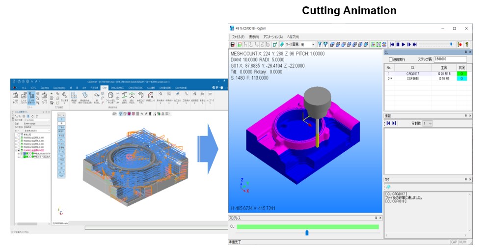
Cutting Animation
The “CuttingAnimation” command performs animation display showing trajectories of cutting tools.
The “CuttingAnimation” command serves the System operators by enabling them to takeover/handover a cast metal (Stock Model), identify and recognize machining-subject areas and machining sequences, and preview a to-be shape ater machining.
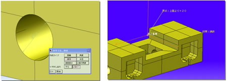
Correction of CAM Figures
This category of functions to improve the quality of paths include the functions of filling in holes and creating support surfaces for machining. They are: the Form_FillingBase" command, the "Form_FillingNotch" command, the "FillingLargeHole" command, the "CollecVertexDeletion" command, the "TopOp_AddBdCrv" command, the "One-time correction" command, the "AlignEndPnt" command, the "SrfEdgeExtension_Separate" command, the "Create_FuzzyOffsetSurface" command, the "SectionalDieBandSurface" command, the "RemoveDupLines" command, the "Curves unification" command, and the "CompulsoryUniteCrv" command.
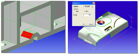
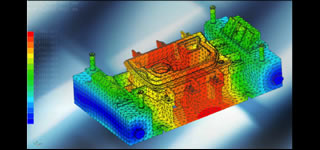
CAM Analysis
CAM Analysis helps the confirmation of shapes and the calculations of paths in a phase of examining manufacturing processes. They are enabled by the "Check_DuplicateSurfaces" command, the "SimpleUndercutCheck" command, the "ContainerBox" command, the "Disp_HeightDim" command, the "FigureRetrieval" command, the "GeomCheck" command, the "ConvertToFreeSrf" command, the "ConvertToAnalyticSrf" command, and the "Reduce_BaseSrf" command.
CAM Dimensions and Annotations
The functions of 'CAM Dimensions and Annotations' display dimensions of shapes and 3D annotation data and also output them in machining instruction manuals and so on. They are performed by the commands: the "RefDim_Create" command, the "RefDim_DispON" command, the "RefDim_DispOFF" command, the "3DAnnotation_Create" command, the "3DAnnotation_Change" command, the "3DAnnotation_Delete", the "3DAnnotation_Move" command, the "3DAnnotation_ChgProperty" command, the "3DAnnotation_DispON" command, and the "3DAnnotation_DispOFF" command.
If you have any inquiries about our product or would like to request a visit to your place for explanation or demonstration, please use the inquiry form.
![]() Inquiry form
Inquiry form

 Official site