Function(PRESS DIE)
![]()
![]()
![]()
![]()
![]()
![]()
![]()
![]()
Function(PRESS DIE)
PRESS supports designing press dies. It has three key capabilities: design support, modeling support, and post-process support.
The post-process support is further categorized into capabilities of solid verification, creation of drawings, data for order placement, and coordination of machining.
PRESS’s dedicated commands support the creation of back surface and sectional dies, selection of springs, and placement of standard parts, based on the product shapes during the initial stage of designing.
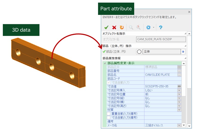
After the designing is finished, parts lists can be automatically created through the use of parts attributes.
Also, drawings can be checked by executing the commands of interference test and die structure verification. Furthermore, CAM system can be coordinated through the use of machining features.
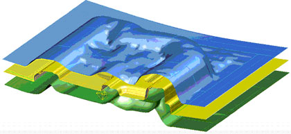
The "Create_FuzzyOffsetSurface" command
This command creates back surfaces that are needed in order to create a Structure based on a panel shape.(Note: a Structure refers to a ferrous die that accepts a press die 'Insert'.)
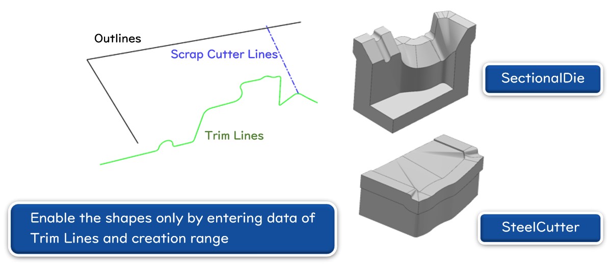
Create Sectional Dies and Create Steel Edges
The "CreateSectionalDies" command and the "CreateSteelEdges" command enables the System operators to quickly create shapes referred to as sectional dies and steel edges that support complicated Trim Lines such as Scrap Cutter Lines by making simple inputs in the command windows.
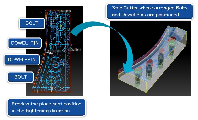
Bolts and Dowel Pins Automatic Placement
The "BoltsandDowelPinsAutomaticPlacement" command automatically identifies the size of subject solid, and automatically place bolts and dowel pins of appropriate sizes and quantities.
The "BoltsandDowelPinsAutomaticPlacement" command enables the System operators to specify a certain area out of an end of edge where bolts and dowel pints are rejected by making numerical inputs in the command window.
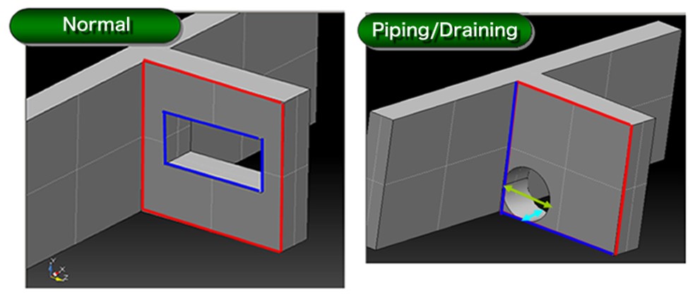
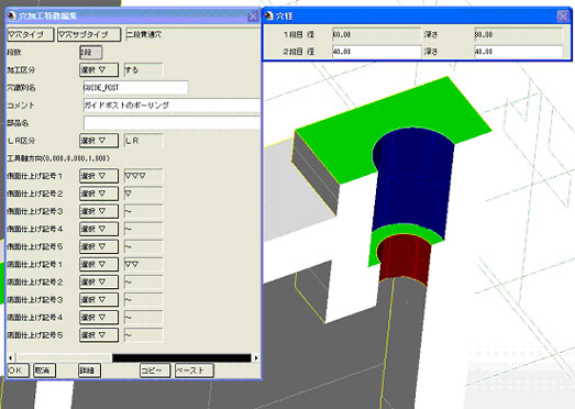
The "CastHole" command
Cast holes can be made by intuitive operations.
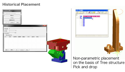
Standard parts and constituent parts such as Guides and U grooves can be placed by trial-and-error attempts.
The attempts can be repeated till the positions are fixed during the Initial Stage of Consideration. These commands support the process.
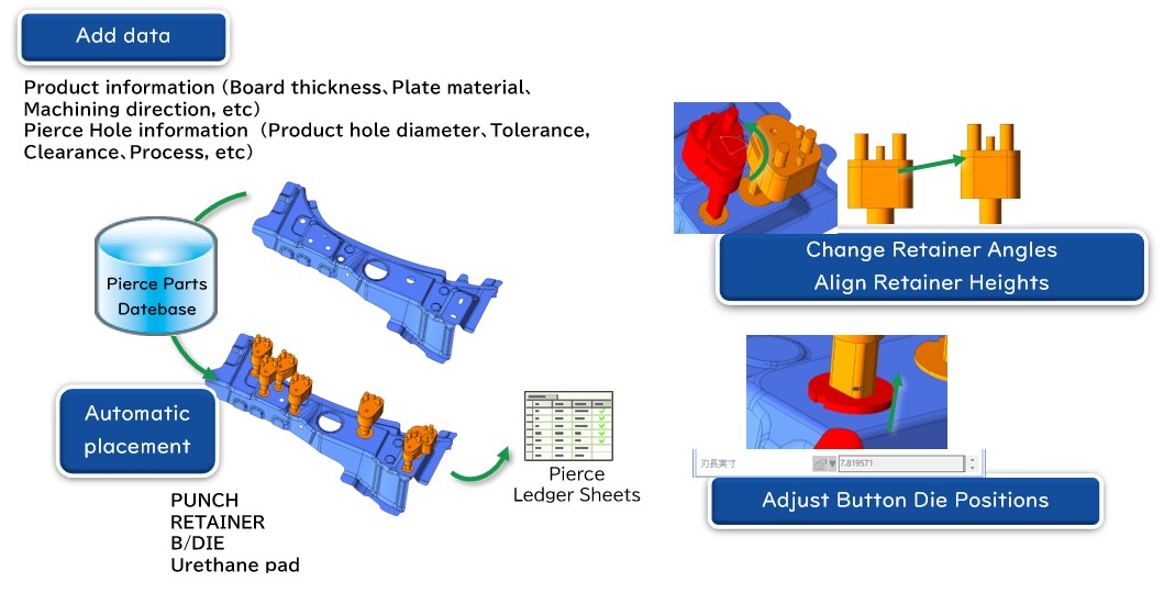
The "PierceAutomaticPlacement" command enables the System operators to previously register Product Panel Data and Pierce Hole Data. The System automatically positions Pierce Parts on the basis of the data. This Command can export Pierce Holes and other data to CSV files.
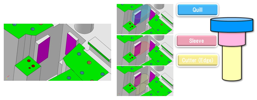
The “ShapeCreation” command dedicated for the Press Die modules serves the System operators to design the feature structures of press die below.
Information can be added to the items that should be listed on a parts list,
such as part name, part number and manufacturer name. Also, each item can be customized.
Machining features for plane surfaces, curved surfaces and holes can be added and transmitted to CAM.
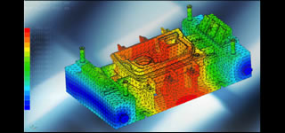
This capability supports die verification such as interference check, press composition verification, and scrap fall consideration.
The "MachiningLimitConfirmation" command enables the System operators to previously check product designs in order to know unmachinable positions.
The commands creates parts lists through the use of the added attributes of parts.
he dedicated commands supports a creation of 2D drawings. They create balloons based on parts attributes, and create finish symbols based on machining features.
If you have any inquiries about our product or would like to request a visit to your place for explanation or demonstration, please use the inquiry form.
![]() Inquiry form
Inquiry form


 Official site